I stopped drawing windows. (the drawings were already there)
Seven checks. Five prompts. A window schedule that proves its own sections.
Window schedules eat my week. Every project. The same job.
Redraw the same awning for the fifth time. Add up the daylight sizes by hand. Chase a mullion span through a manufacturer's book. Copy a schedule out of the last job and hope nobody changed the suite since.
It is not hard work. It is just slow, repetitive, and easy to get quietly wrong.
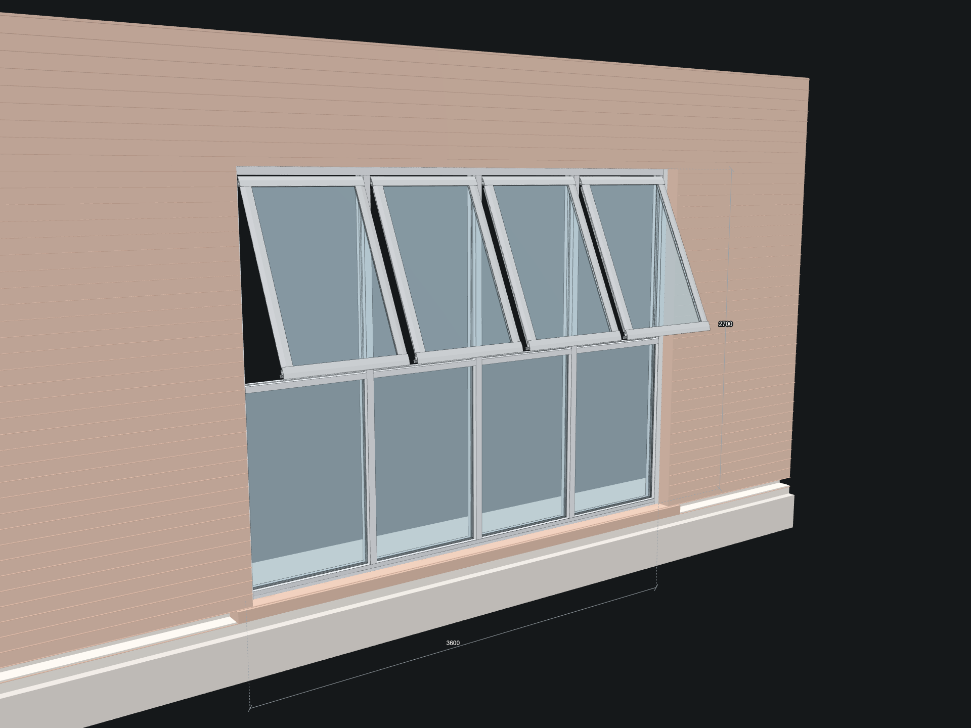
So I built a tool that does it. It draws the window in 3D from the real extrusions, sets out the daylight sizes, checks the mullion span, and exports a schedule I can put on a drawing.
Then I made it prove every section against the manufacturer's own published numbers. That part matters more than all the rest.
Two things before we start
- Save this. The 7 checks below are worth 10 minutes even if you never build a thing.
- Send it to the person in your office who owns the window schedule. They will recognise every trap.
a 101.6mm aluminium window suite centre pocket double glazed framing, with a the awning insert, sitting in a 250mm brick veneer wall. An ordinary Australian commercial window. It is on a lot of jobs I do.
Check 01The sections: lifted, not modelled
Like tracing a detail off a PDF, versus being handed the DWG.
The first instinct is to reach for the Revit family. It is the manufacturer's own file, so it should be the truth.
It is a dead end for geometry. Revit keeps its solids in a proprietary binary partition. The only parameters you can actually read are Rough Width, Rough Height and Default Sill Height.
Useful for a schedule. Useless for a section.
The manufacturing DWG is the real source. Every extrusion drawn at full size, with its published data printed next to it. the manufacturer calls it the Extrusion Elevation Detail. Every major supplier publishes one.
There is a catch. These files are AC1032, and the converters mangle the newer ones. Duplicate handles, broken polyline grouping. Every strict DXF reader throws before it reaches the geometry.
So the first thing built was not a window. It was a tolerant scanner that walks the raw group code stream and pulls out only what a profile needs.
Use it for: real geometry instead of an approximation you drew from a printed dimension.
I have a manufacturer's extrusion elevation DWG at [path]. Convert it to DXF and extract the closed profile outlines.

The file is likely AC1032 and strict DXF readers will fail on it, so write a tolerant scanner that walks the raw group code stream and pulls out closed polylines with their bulges, plus the annotation text. Do not use a strict parser.

Keep the bulges. They are the arc segments, and without them every radius in the section becomes a chord.
The one mistake: trusting the Revit family because it came from the manufacturer. It is a scheduling object with a box for geometry.
Check 02The proof: two numbers that fingerprint a shape
Like checking a beam against the section properties table, instead of scaling it off the drawing.
This is the part I did not expect to matter most.
A drawing sheet has 40 or 50 closed shapes on it. Some are extrusions. Some are dimension ticks, hatch fragments, pieces of a title block.
How do you know which shape is the head section and not part of a leader line?
You could match by layer. You could match by position on the sheet. Both are guesses, and both break the day the manufacturer reissues the drawing.
But the drawing prints two numbers next to every extrusion.
Mass in kilograms per metre. At an aluminium density of 2710 kilograms per cubic metre, that is the exact cross sectional area of metal.
Anodising perimeter in millimetres. That is the exact length of the outer boundary.
Area and perimeter together are close to a fingerprint. A shape that agrees with both, to a fraction of a percent, is the shape on the label.
So the matcher ignores layers and positions completely. It measures every closed ring on the sheet and asks which one agrees with the published numbers.
Every profile on the sheet, the head and jamb, the sill, the mullion, the transom, the sash and the subframe, matched its published figures on both numbers.
Area agreed to better than a tenth of a percent. Perimeter to within a quarter. Six for six.
Then a third check that was never part of the plan.
The manufacturer also prints an Ixx for the structural members. So I computed the second moment of area from the extracted geometry and compared it.
Six profiles. Every one inside 0.1%.
Three independent quantities agreeing to within two tenths of a percent. That is not a coincidence. That is the section.
It settled a convention question for free, too. The published Ixx is always about the axis using the 101.6mm through wall depth as the lever arm, which is the wind resisting direction. Worth knowing before you put it in a span calculation.
Use it for: knowing you have the right section, not a confident looking wrong one.
Next to each extrusion the drawing prints a mass in kg/m and an anodising perimeter.

Use those to identify the profiles instead of matching by layer or by position on the sheet.

Compute cross sectional area from the mass at 2710 kg/m3. Compute the perimeter from the ring. Match each published code to the closed ring that agrees with both to better than 1.5%, and report the error on each as a percentage.

If the drawing also prints an Ixx, compute the second moment of area from the extracted geometry and compare. Tell me which axis it corresponds to.
The one mistake: matching by layer name. Layers are how the draftsperson organised the sheet, not what the shape is.
Check 03The trap: two drawing conventions
Like a hatch drawn as a boundary, next to one drawn as a region. Same picture, different object.
Two conventions are in play on the same sheet, and mixing them up costs you sections.
Most extrusions are drawn as one keyhole ring that already walks into its own hollow chambers. Run the area formula and you get the metal area directly.
The rest are drawn as a solid outer boundary, with the chambers as separate closed rings sitting inside it. Same formula, wildly wrong answer, because the voids are still counted as metal.
The anodising perimeter is the outer boundary either way. So the fix is to match on perimeter first, then find the chambers by containment and subtract them.
That one change recovered three sections I had already written off as unrecoverable.
There was a second trap underneath it, and it cost me two more. Identical chamber shapes repeat all over a sheet. My code was deduplicating rings by shape, so the chamber sitting inside the profile being matched kept getting thrown away as a duplicate of one somewhere else on the page.
Small bug. Two sections.
Use it for: recovering the hollow sections that a naive extractor silently drops.
Some profiles in this drawing are single keyhole rings that already include their hollow chambers. Others are drawn as a solid outer boundary with the chambers as separate closed rings inside it.

The published anodising perimeter is the outer boundary in both conventions.

So match on perimeter first. Then find any rings contained inside the matched ring, and subtract their areas before comparing against the published area.

Important: deduplicate rings by position as well as by shape. Identical chamber shapes repeat across the sheet, and keying only on shape throws away the chamber that sits inside the profile you are matching.
The one mistake: assuming a closed shape on a manufacturing drawing means solid metal.
Check 04The assembly: the manual, not just the drawing
Like having the product datasheet but not the fixing detail. You can specify it and still build it wrong.
The drawing gives you sections. It does not give you assembly.
I built an entire awning window on the wrong parts. Twice.
The sections extracted perfectly. Both verified against their published numbers. Both belonged to a different frame in the same range.
One of them is labelled, in the same DWG, as belonging to a different suite. I had matched the geometry correctly and then fitted it into this suite's pocket, because I never read the label properly.
The technical manual has a page for exactly this pairing. It names the right two parts. It also dimensions the set out as three simple formulas: the sash and glass sizes come off the frame width, and the sash height off the daylight opening.
Three dimensions that replaced a day of guessing.
The second mistake was the more interesting one. The correct sash is drawn in the DWG but never labelled, so there were no published numbers next to it to match against. It looked absent.
It was not absent. The manual's extrusion pages carry the data for the whole range, labelled on the sheet or not. Its published mass and anodising perimeter are sitting right there. Feed those two numbers in and the shape identifies itself.
Worth knowing: three sashes in that range share an identical envelope, and only the anodising perimeter separates them. Pick the wrong one and it still looks completely plausible on screen.
Use it for: not fitting a part from a neighbouring suite and never noticing.
Read the typical details section of this manual: [path to the technical manual PDF].

For each assembly, list the part codes named in the detail, and any set out dimensions given as formulas.

Then check the parts I am currently using against that list, and tell me plainly where they disagree.

If a part is named in the detail but has no label in the DWG, find its published mass and anodising perimeter in the manual's extrusion pages and use those two numbers to match it against the unlabelled rings.
The one mistake: assuming the drawing contains the assembly. It contains the parts. The manual contains the building.
Check 05The span: calculated, or looked up
Like the difference between a span you can calculate and a bushfire rating you cannot. One is arithmetic. One is a test certificate.
This is the same idea that governs a wall type, and it applies just as hard here.
Deflection is arithmetic. A mullion is a simply supported beam carrying wind over its tributary width. Held to span over 250, which is the usual limit for framing that carries glass, the longest it can run is:
L = cube root of ( 384 × E × I / (250 × 5 × w) )
E is 70,000 MPa for aluminium. I is the second moment of the actual section. w is the serviceability wind pressure times the tributary width.
Because I comes from the geometry rather than a table, the number moves when the member does. Change the mullion and the allowable span changes with it, in the same breath.
What is not arithmetic: the ultimate limit state, the glass, the fixings, the hardware. Those are properties of tested systems and published tables. The tool does not touch them.
So it does what the wall tool does. It calculates what can be calculated, states the basis on screen, and stays quiet about the rest.
Use it for: a defensible span in front of a facade consultant, instead of a rule of thumb from a job three years ago.
Separate what you can calculate from what has to be looked up.

Calculate: mullion and transom deflection. Treat the member as a simply supported beam carrying wind over its tributary width, limited to span/250, using the second moment computed from the actual extracted section. Let me set the serviceability wind pressure. Always show the span the member is good for at the current bay width, and state E, the limit and the pressure on screen.

Do not calculate: ultimate limit state, glass thickness, fixings or hardware capacity. Those come from tested systems and published tables.

If I ask for one of those, say what document it comes from instead of producing a number.
The one mistake: a span table copied from an old job. The table was right for the section it was written for.
Check 06The output: a schedule you can issue
Like the difference between a sketch and a drawing. One explains an idea. One goes in a set.
A 3D window is a nice picture. It is not a deliverable.
The deliverable is the schedule, laid out the way it reads on a sheet: one column per window type, one row per field, elevation at the top.
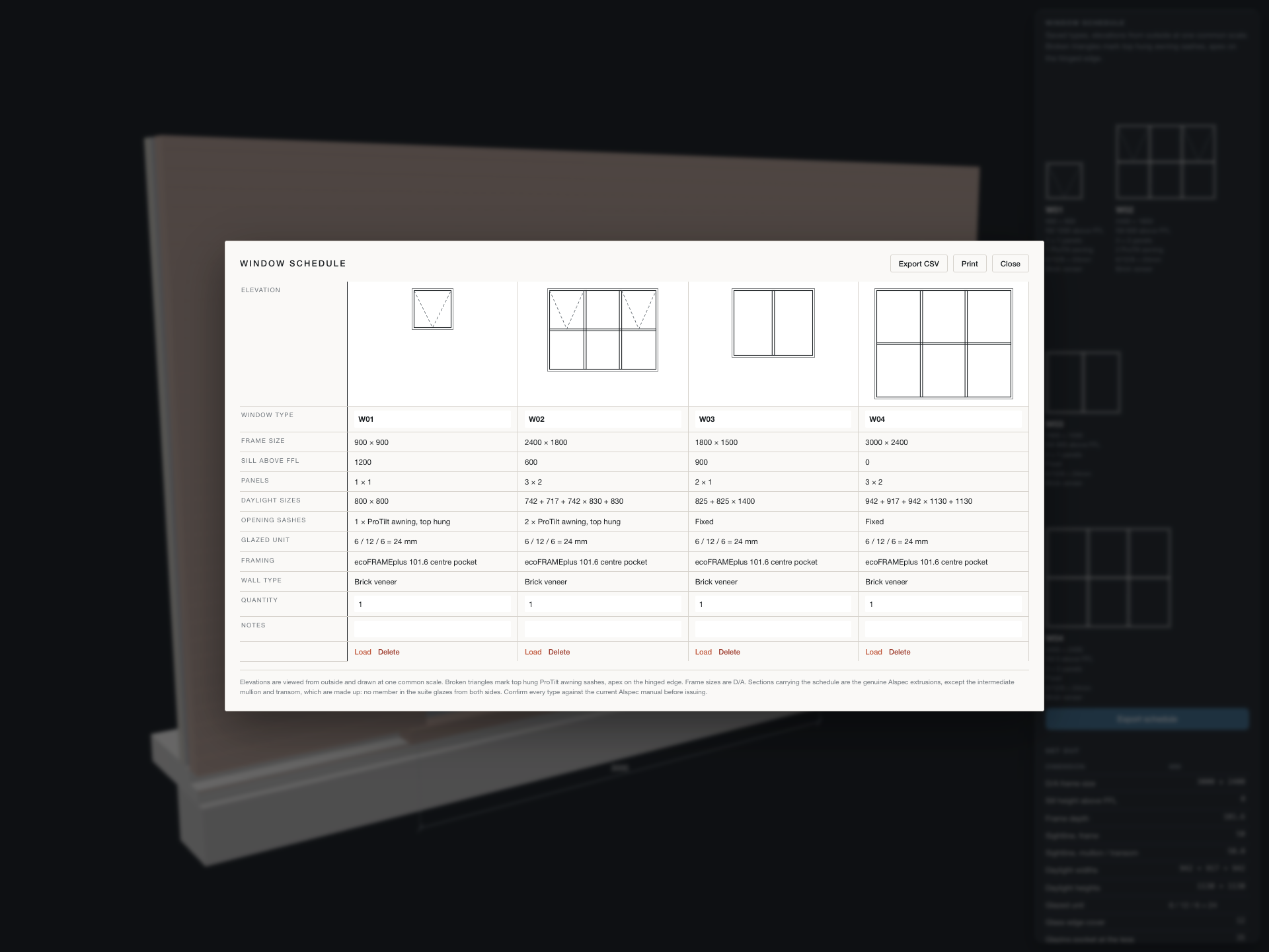
Mark. Frame size, which is D/A. Sill above finished floor. Panels. Daylight sizes. Opening sashes. Glazed unit. Framing. Wall type. Quantity. Notes.
The daylight sizes are the ones people leave off, and they are the numbers the glazier actually orders to. They come out of the same set out the 3D model uses, so they cannot drift from the geometry.
The elevations all draw at one common scale, so a 3000 wide genuinely reads three times a 1000 wide. Marks, quantities and notes are editable in place. It exports as CSV in the same column orientation, so it drops onto a schedule sheet without being transposed. Or it prints.
Use it for: the thing you were going to retype anyway.
The one mistake: building the 3D and stopping. The 3D is the part that impresses people. The schedule is the part that saves you a day.
Check 07How it got built, in one session
Like briefing a graduate who types very fast, never gets bored, and has genuinely read the whole manual.
I built this with Claude Opus 5, in Claude Code. I did not write a line of it.
That sounds like the point. It is not.
The model wrote every line of code, and every line of code was easy. What made the tool correct was a list of things it had no way of knowing, that I had to say out loud.
Jambs run continuous full height. The head and sill are cut between them.
Every pocket in this suite is 35.0mm at the glazing legs, on a 50.8mm centreline. So every fixed panel glazes on one plane.
Glass edge cover is 12mm. The pocket floor is at 21, the setting block is 17 high, and 21 plus 17 puts the glass edge exactly where the detail dimensions it.
In brick veneer the window sits between the brickwork and the lining, and the frame itself closes the 50mm cavity.
An awning is top hung. It hinges at the head, on the outside face, and the bottom swings out.
None of those are code. All of them are the job.
The other half of the workflow is reviewing what you can already review.
I cannot audit a geometry matcher. I can look at a window and see that the sash has flown off its hinge, that the mullion is reading as two thin members instead of one, that the subframe is eating the daylight opening.
Every one of those was a real bug. Found by eye in a couple of seconds. Described in a sentence. Fixed.
One of them turned out to be a sign error in the hinge matrix, which had been quietly throwing the sash 860mm sideways. I could not have found that in the code. I found it because the window looked wrong.
Vibe coding worked here for one reason: I was the person who could tell when the answer was wrong.
If you want to try this, start with something you already check by hand every week, so you can spot a bad answer instantly. I did the same thing with a wall type builder before this one (chiangning.net/resources/wall-type-builder) and a floor plan to LEGO builder before that (chiangning.net/resources/lego-room-builder).
Claude Code is the surface that does it. If you have only ever used the chat window, the five surfaces is the map (chiangning.net/resources/five-surfaces-of-claude). And if you want the repeatable version rather than a one-off, that is what a Skill is (chiangning.net/resources/what-is-a-skill).
The honest partWhat this cannot do
Two members in my model are invented.
No section in this suite takes glass from both sides on a single member, so the intermediate mullion and transom are made up: plain tubes carrying the suite's own pocket geometry. They print the words made up in the verification table and in the schedule footer, every single time. The real candidates are sitting in the manufacturer's loading tables and I have not chased them yet.
The sash glazing bead is not modelled. Neither are the sub-head, sub-sill or two part sub-jamb. That last one matters: the installation manual makes the sub-sill a drainage tray in a designated wet area, left open at the front for pressure equalisation. It is not decoration, and it is missing.
The span check is deflection only. Nothing about ultimate limit state, the glass, or the fixings.
And it is not a shop drawing. It sets out and it schedules. Every type still gets confirmed against the current manufacturer's manual before it is issued.
The scarce thing was never the code. It was knowing that one of those adaptors belonged to a different suite. The model built the tool in a session. It could not have told me a single rule that made the tool correct.
Build the thing once.
Comment "WINDOW" and I will send you the build: the extraction method, the verification rules, and the 5 prompts above in one file.
And if someone in your office owns the window schedule, send this to them. They have been doing it by hand for years.