ArchiCAD + Opus 5 is insane. (until you ask it to place a sofa)
Architects: it drafts, it does not design. One free connector, one raster floor plan, one evening. Here is exactly what came out well, what came out wrong, and which of the two mattered more.
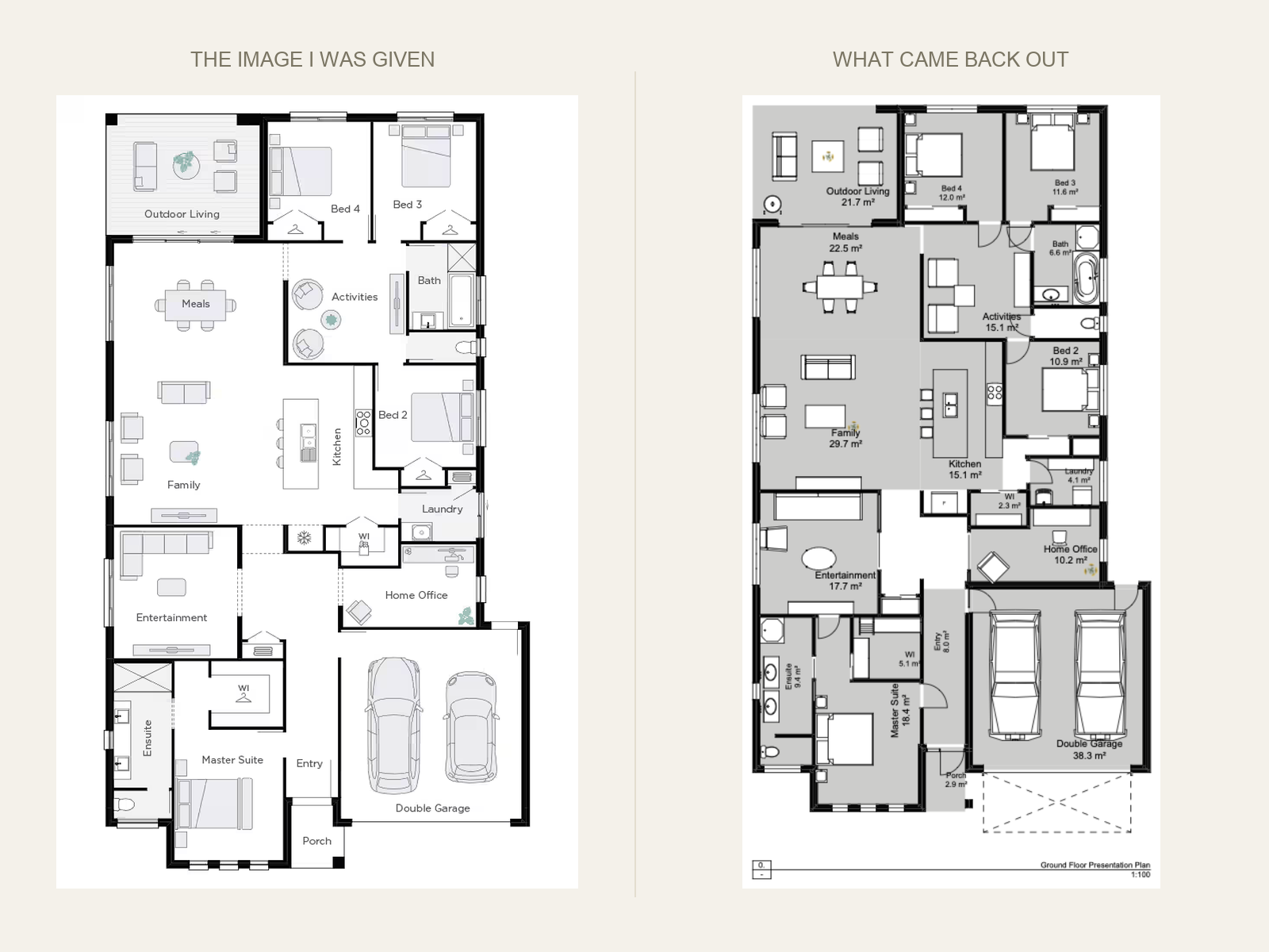
I did not build anything for this one. I just watched.
I gave Claude Opus 5 a single image of a floor plan, no scale bar and no dimensions on it, and asked it to trace it into ArchiCAD as a properly drafted model. Real walls, real doors and windows, real room tags, a dimension set, a roof.
It has no eyes and no hands on the keyboard. What it had was Tapir, a free, open source add-on that exposes ArchiCAD's own JSON API as a set of callable commands. Claude is not talking to ArchiCAD's interface. It is talking to the same programmatic layer a BIM manager would script against, over a local port, with the file open on my screen the whole time.
Two and a half hours later I had a dimensioned, roofed, furnished single storey house file. Some of it I would issue as is. Some of it I had to catch and fix by eye. The line between those two turned out to be the actual finding.
It also changed how I think about what I was using. Somewhere in that session I stopped calling it a tool in my head. A tool does the job you already worked out, once you hand it your own intelligence, your own dimensions, your own sequence of steps. Nothing here was handed over that finished. I gave it one picture and a paragraph of brief, and it decided for itself to decode the image, measure a pixel grid, and cross check the scale against a real garage width, before it drew a single wall. That is a judgement call, not a lookup. That is what makes it an agent rather than a tool, and it is also exactly why the furniture went wrong later. An agent that makes its own calls will sometimes make the wrong one.
A single storey, four bedroom house traced from one plan image: 51 walls in two real composites (250mm brick veneer, 90mm stud), 22 doors and 15 windows from the AU library's own favourites, 19 zoned and labelled rooms, a full grid and dimension set outside the plan, a 15 degree hipped terracotta roof with a 600mm eave, and close to sixty furniture objects.
Part 01The connection: what Tapir is, and is not
Not a Claude feature. A door somebody else left open, that Claude can now walk through.
Tapir is a community add-on for ArchiCAD, built and published independently of both Graphisoft and Anthropic. It sits inside ArchiCAD and answers JSON commands on a local port, the same shape of interface ArchiCAD itself exposes to Python scripts and BIM automation tools.
What changed is not the API. What changed is who can drive it. Point an MCP server at that port and Claude can call CreateWalls, CreateDoors, CreateZones, CreateRoofs, the same verbs a plugin developer would use, in the same session where I am looking at the floor plan on screen.
Nothing about this is ArchiCAD specific in principle. Rhino, Revit and Blender all have the same shape of scriptable API, and the same MCP pattern applies. ArchiCAD is simply the one I had a live file open in.
Use it for: anything you would otherwise script by hand against a CAD API, described in a sentence instead of written in Python.
Install Tapir and connect Claude, step by step
A. Put the Tapir add-on into ArchiCAD
- Download the Tapir add-on for your exact ArchiCAD version from the Tapir releases page on GitHub. It is free and open source, maintained independently of Graphisoft, and each build is compiled against a specific ArchiCAD release (28, 30, and so on), so take the one that matches yours.
- Save the downloaded add-on file somewhere permanent, not a Downloads folder you periodically clear. ArchiCAD loads it from wherever it sits.
- In ArchiCAD, open Options > Add-On Manager. Go to the Edit List of Available Add-Ons tab, click Add, browse to the file you just downloaded, and click OK.
- Restart ArchiCAD. Tapir now lives inside ArchiCAD and answers JSON commands on a local port whenever a project is open. With no project open there is nothing to connect to.
B. Point Claude at it (the MCP server)
You need Python 3.12 or later and the uv package manager, plus an MCP client. I used Claude Code; Claude Desktop works the same way.
- Claude Desktop: edit claude_desktop_config.json (macOS: ~/Library/Application Support/Claude/, Windows: %APPDATA%\Claude\) and add the block below. The uvx command fetches and runs the server for you, so there is nothing else to install.
- Claude Code: instead of the JSON, run one line in your terminal: claude mcp add ArchicadTapir -- uvx --from tapir-archicad-mcp archicad-server
- Fully quit and reopen Claude (or restart the MCP connection) so it picks up the new server, with your ArchiCAD project open on screen.
- Before asking for anything real, confirm the link: ask Claude "which ArchiCAD projects do you have running?" It should call discovery_list_active_archicads and name your open file. If it sees the file, you are connected.
{
  "mcpServers": {
    "ArchicadTapir": {
      "command": "uvx",
      "args": ["--from", "tapir-archicad-mcp", "archicad-server"]
    }
  }
}
Keep the file visible the whole session. Nothing here happens invisibly. Every wall, door and object it creates draws in ArchiCAD in real time, in front of you, and you can undo any of it the same way you would undo your own click.
One thing worth knowing going in: there is no screenshot command in this API. The only way to actually review what got built is to publish the model to PDF and look at that, which is also how I caught the furniture problem in Part 04.
Part 02Tracing a picture into real geometry
Like handing a graduate a scanned drawing and a scale rule, and getting back a set-out plan.
The starting point was one AVIF image. Not a DWG, not a PDF with real coordinates in it, a picture. No scale bar, no dimension string, nothing but a labelled floor plan drawn to look nice.
The only way in is measurement. It read the pixel grid of the image, found the double garage in it, and calibrated the whole drawing off the one dimension it could be reasonably sure of: a double garage is close enough to 6.0 metres wide, always. Every wall, door and window position after that came from pixel offsets against that one calibrated scale.
It came back believably close. Room areas matched what a house of that footprint should read, door and window widths landed on real catalogue sizes, and the whole thing squared up into a rectangle that closed correctly on both axes. I did not have to nudge a single wall back onto its neighbour.
Use it for: getting a rough plan, a hand sketch, or a superseded PDF into real geometry, fast, without redrawing it by hand first.
Use the Archicad MCP and trace this floor plan for me. Use your best ability to draft appropriate sizes to call rooms. Insert doors, windows, furniture objects. Use accurate wall thickness. Include all room notations. Output must be a professionally drafted floor plan.
What actually happened: before it placed a single wall, it decoded the image itself, cropped it into a measurement grid, and cross checked the scale against a known real-world size. That step was not asked for. It just did it.
Part 03What it is genuinely good at
The tasks nobody wants on their timesheet. It did not complain once.
Once the geometry existed, everything that followed was administration, and this is where it earned its keep.
Asked for dimensions on every wall, it built a full grid, letters one way and numbers the other, dropped the bubbles outside the building, chained every wall centreline into a dimension string, and closed each chain against the overall. It came back to scale. The numbers add up against each other and against the drawing, which is the part that is tedious to check by hand and easy to get wrong.
Asked for a roof, it took a pitch, an eave, and a material, and built one multi plane hip that resolved its own valleys where the garage wing meets the main volume, sitting on a real composite construction rather than a drawn line.
Layer names, story assignment, sheet setup for the layout book, publishing to PDF for review: all of it landed correctly, all of it on the first pass.
Use it for: exactly the menial, mechanical parts of documentation. Dimension strings, grids, sheet administration, layer housekeeping. The stuff that eats an afternoon and asks nothing of your judgement.
Add dimensions to all the external and internal walls. All dimensions must be properly inserted outside the floor plan. Insert indicative lines as grid lines.
Add a roof over this building. 15 degree pitched roof, terracotta roof. 600mm eaves overhang throughout.
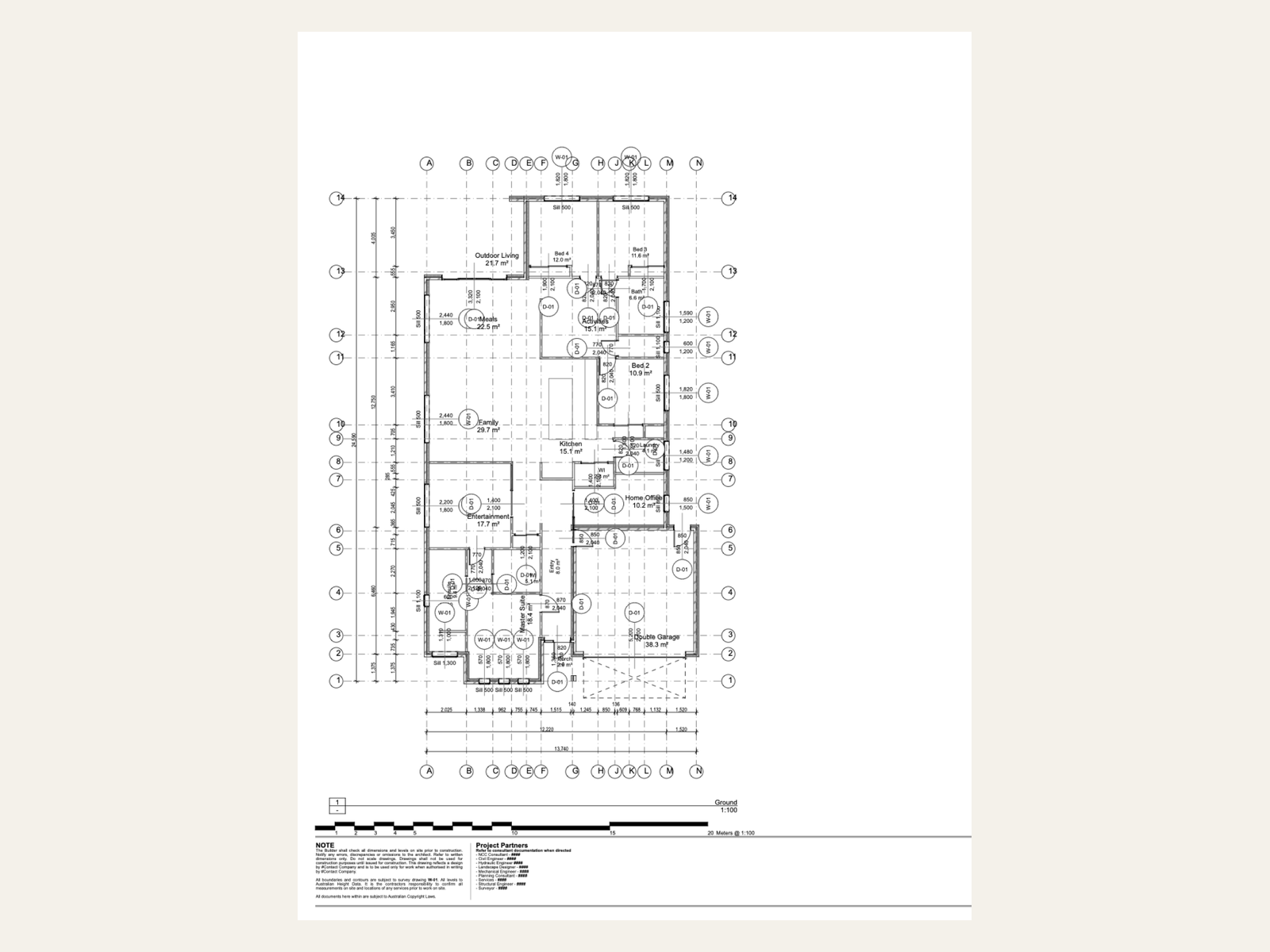
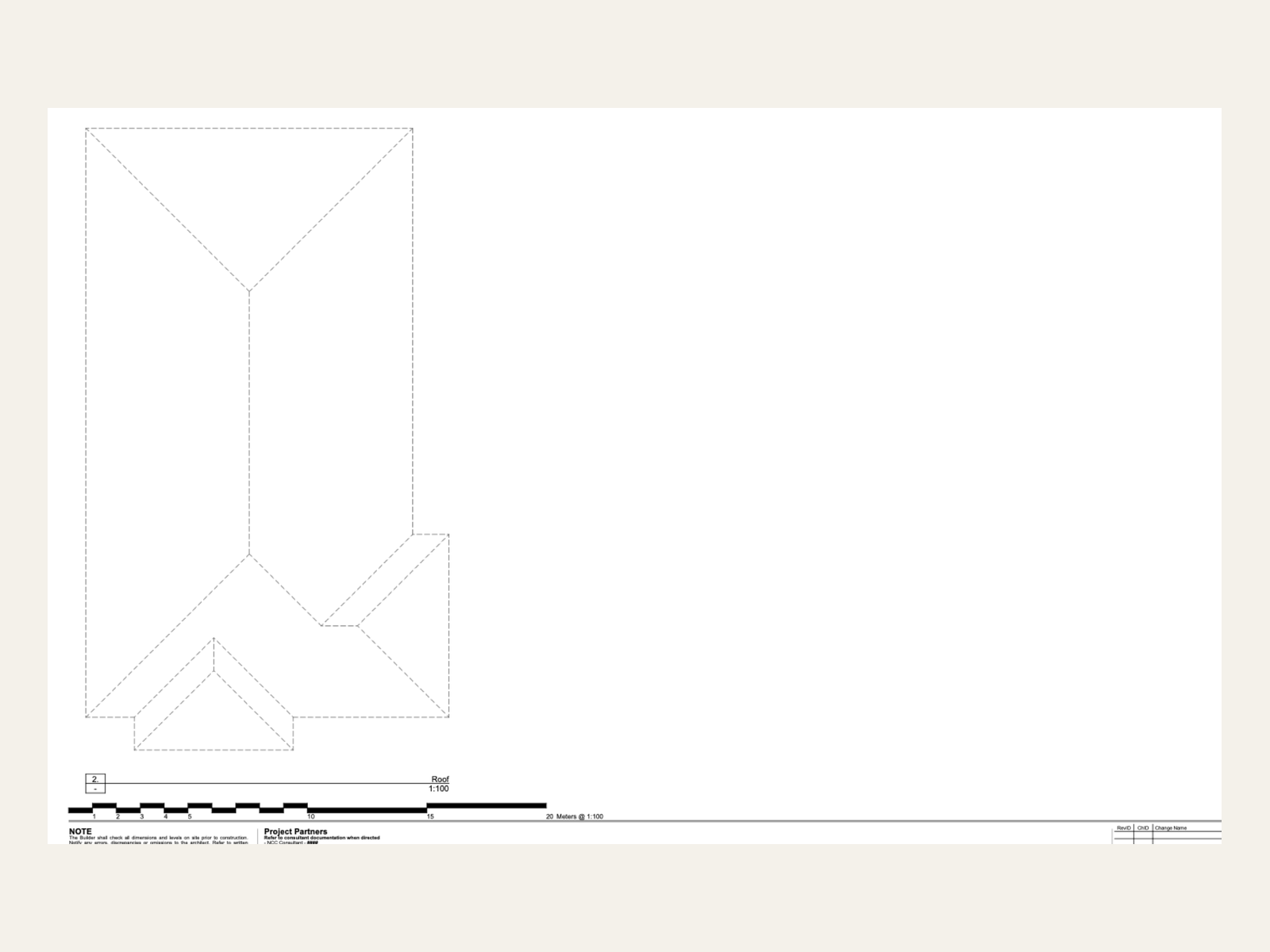
Grid, dimension chain and 600mm eave overhang, all correct without a second prompt.
Part 04Where it went wrong: design judgement
Told to place a car, it made something the right area and the wrong shape.
Furniture is where the whole exercise turned honest. Asked to fill the rooms, it placed beds, sofas, a kitchen bench, two cars in the garage. On the plan it looked plausible at a glance, room by room, object by object.
Then I looked properly. Both cars had been squeezed to the wrong proportions, a car's length compressed into its width. Wall-backed furniture, sofas, the fridge, the vanities, the bed heads, was facing into the wall it should have had its back against, on more than half the pieces in the house. The bathtub had drifted out past the wall it was meant to sit against, into the side yard.
None of that was a geometry failure. The measurements it used to size and place things were reasonable. What was missing was the same thing a junior drafter is missing on their first week: nobody had told it which way round a sofa faces, or that a car's long axis is its length, not whatever axis happens to be convenient.
The lesson: do not expect it to make good design choices unsupervised. Loose instructions like "furnish this room" get you object count, not orientation. It has no default notion of which way a bed's headboard goes.
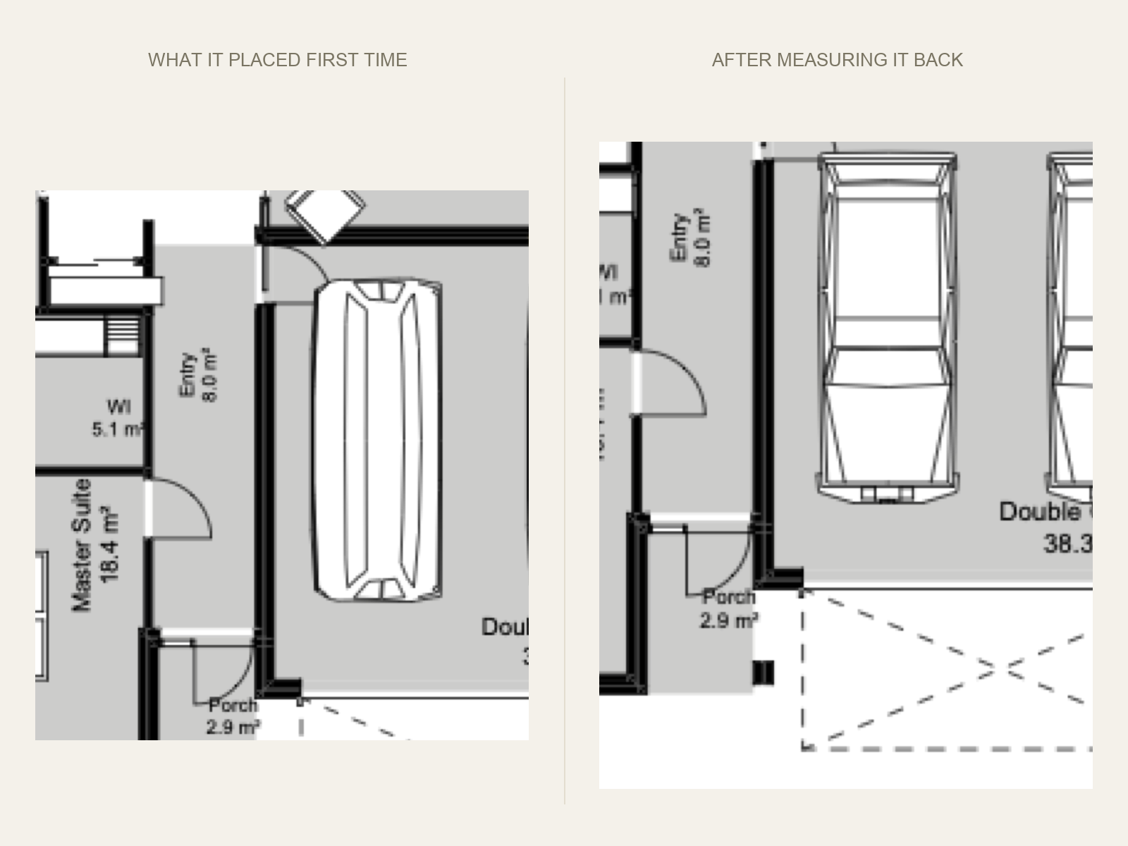
Left, first pass: right length, wrong axis. Right, after correction: measured, rotated, and snapped to the bay.
Part 05Catching it: the fix was one more prompt
The failure was not fatal. It was recoverable, and recoverable fast.
This is the part worth saying plainly: a bad first pass on furniture is not a dead end. One more prompt, describing exactly what was wrong and naming the pieces, was enough to have it go back, place a test grid of every object in an empty area first to read its true orientation and size, and then rebuild the whole room set against that.
The pattern that actually worked was place, measure, then snap. Rather than trusting an assumed size and rotation up front, it placed each object once, read its real bounding box back from the model, and only then moved it so the correct edge landed on the correct wall. That is a slower way to do it. It is also the only way that reliably closed the gap between "looks right in a screenshot" and "is actually against the wall."
Use it for: knowing that a bad pass on placement or orientation is a correction prompt away, not a reason to give up on the workflow.
There's something wrong with the furniture. Some of them seem to be facing the wrong way. The 2 cars in the garage I believe you need to rotate 90 degrees and resize them accordingly. Use your best judgement to rectify these. Pay attention to how all furniture are placed. Pay attention to the bathtub, it seems to be in the wrong spot. Use your best effort.
What it needed first: before touching a single piece of furniture again, it placed one of every part type in a blank area, read back its real footprint and facing convention from the model, and only then went back to fix the rooms. It had never checked that on the first pass.
Part 06The honest split
A very fast, very tidy drafter. Not yet a designer.
Put the two halves of the evening side by side and the split is clean. Everything with a correct answer that can be checked by arithmetic, a dimension closing, a grid squaring up, an eave measuring exactly 600, a roof pitch reading exactly 15 degrees, came back right and stayed right. Everything that needed a design instinct, which way does this face, does this look like a room a person set up, needed a second pass and a human eye.
It has no way to look at its own output. There is no screenshot command in this API. The only way I could actually see what it had built was to have it publish the model to PDF and rasterise that, which is also, not coincidentally, the only reason I caught the furniture problem before it went any further. Reviewing the visual result was mine to do, every time, and it stayed mine to do.
None of this is a reason to skip the mechanical half. A dimension set and a roof correctly built in minutes, on a file I would otherwise have set out by hand, is real time back. It just is not the same claim as "it can design a house," and I would not want anyone reading this to conflate the two.
Part 07Two and a half hours, against a graduate's three or four
Faster than the person you would have given this to. Not yet better.
The whole session, trace, dimension, roof, the furniture pass and the correction pass after it, ran to about two and a half hours of actual working time. A graduate architect handed the same plan image and the same brief would reasonably take three to four hours to produce the equivalent drawing set.
I would not call that a win on quality. A graduate, given that time, would set the furniture facing the right way the first time, because they already know which way a sofa faces. What the graduate would not necessarily give you in three hours is a fully squared dimension chain on every wall, a correctly resolved hip and valley roof, and a room schedule with areas that foot up, all self checked. That half came out faster and to a tighter tolerance than a first-pass graduate drawing usually does.
So the honest comparison is not faster and better. It is faster on the mechanical half, and behind on the judgement half, in a way that a normal review pass catches.
Which is exactly what week 1 looks like for anyone you have ever hired.
The honest partWhat this cannot do, yet
It cannot look at the model and tell you it looks wrong. Every visual check in this session, the facing, the car proportions, the bathtub, was caught by me looking at a rendered PDF, not by anything on the model side flagging itself.
It has no default sense of furniture convention, headboard against the wall, sofa facing the television, car nose to the wall it reverses out from. Those are things you have to say, or things you have to catch afterwards.
The trace itself is only as good as the source image and the one calibration dimension it could find. A plan with no recognisable reference size would not have worked nearly as well.
And it is not a substitute for a drafter checking the file. Wall composites, door and window schedules, and every dimension were things I read back and would still confirm against a real project brief before this went anywhere near a construction issue.
Most of what went wrong here was not a reasoning failure. It was missing context that lives in my head and nowhere it could reach: which furniture blocks I actually use and how they are meant to face, what my publisher set and layer combinations are called, how I name a drawing, how I set up a job folder. A Skill is exactly the place that context belongs, and it is the difference between correcting the furniture once and correcting it every single project.
The scarce thing was never the API call. It was someone who could look at the plan, know that a bathtub does not belong in the side yard, and say so in one sentence. Teach that once, in a Skill, and it stops being a per-project cost.
The quirks are a Skill away.
The next build on this is a Skill that remembers the office standard once, my job folder setup, my layer names and drawing numbering convention, my publisher set, and a default furniture library with the facing already correct, so the correction pass in Part 05 does not have to happen again.
If your office is sitting on ArchiCAD, Revit or Rhino and wondering whether an AI connection like this is worth setting up, this is the honest version of what it does today.